Flex Neon Product
Flex Neon Installation
- These illustrations are for demonstration purposes only
- Always follow cut marks provided in user manual
- Only cut on the marks provided on the fixture housing
- When applying linear solutions to a channel, make sure to use an appropriate silicone adhesive between the base of the channel profile and the fixture housing to eliminate stretching over time.
Basic
 |  |  |  |  |
|---|---|---|---|---|
Cutting Mark | Linear Installation | Curve Installation | 180 Installation | 90 Installation |
LSN must only be | Aluminum channel | Aluminum channel | Aluminum channel | Aluminum channel |
Screens | Screens | Screens |
Overview
- Measure the locations that you will be installing the LED Flex Neon. This is necessary to determine the cutting units required for each specific run. Each color and voltage has different cutting parameters.
- Measure and cut Aluminum mounting channel to your required project lengths.
a. Use proper blade for cutting aluminum.
b. Pre-Drill your mounting screw holes prior to mounting.
- Measure LED Flex Neon to the required length.
a. You can only cut LED Flex Neon on the designated vertical slash.
b. Make sure you cut exactly on the slash or the product may be damaged.
- Insert male power pin and slide heat shrink back a few feet, for later use.
a. Make sure your pin is centered in the strands of wire top and bottom.
b. Do not apply too much pressure as the pins are fragile and will bend or break.
c. Male power pins have one side with barbed edges and the other side smooth edges for terminal connection. Barbed edges are inserted in the flex wire.
- Slide the female power feed over the flex and align the male power pin with the female power feed.
a. TIP: Use heat gun to warm the female power feed to make alignment easier.
b. Outdoor applications use water tight long term packing.
- Run a bead of electronic grade silicone around perimeter of the female power feed and LED Flex Neon.
- Pull your heat shrink up and over the Female Power Feed junction and apply heat with heat gun.
a. Our heat shrink contains glue that will bind the LED Flex Neon and Power Feed or End Cap.
b. Be sure enough heat is applied that you can see the glue release and mold to the flex and power feed or end cap.
c. Do not overheat or burn the LED Flex Neon.
d. Do not energize LED Flex Neon until your heat gun joints have cooled and installation is complete!
- Place end-cap or jumper on the end of the run (repeat steps 6 & 7 for end cap and steps 4 through 7 for jumpers)
- Insert LED Flex Neon into aluminum mounting channels.
a. Make sure it seats and clips.
b. When inserting make sure all screws are fully set.
c. For long vertical runs make sure the flex is tied with stainless steel ties around the aluminum tracking every few feet. This is required due to the fact that PVC and Aluminum have different rates of expansion and contraction which could cause the product, for a small period of time and perfect condition, to become loose.
Before Installation
What you need:

Not Provided
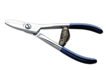
Sharp Blade Cutting Scissor
Not Provided
Electronic Grade Silicone
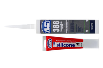

Provided
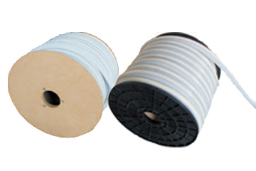
PRODUCTS IN ROLLS
Accessories
 |  |  |  |
|
|---|---|---|---|---|
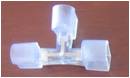
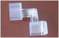
Power Connector | PIN Connector | Straight Connector | T Connector |
|
LSN-PCR | LSN-MRF | LSN-MR | LSN-TR |
|
 |  |  |  |
|
 |  |  | ||
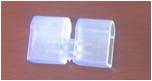
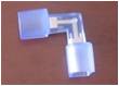
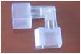
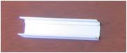
End Cap | L Connector | Mounting Channel | ||
LSN-ECR | LSN-LR1 | LSN-MC | ||
 |  |  |  |  |
INSTALLATION PROCESS
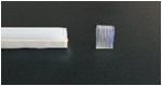
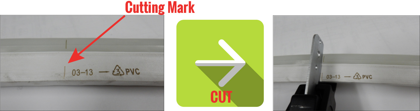
1. Cutting LED Flex Neon
1. Cutting LED Flex Neon
Locate the cutting mark on the side of the LED Flex Neon. This will be designated by a vertical dashed line. Using your anvil sheers, make an even cut through the LED Flex Neon exactly on the mark. If you are off the mark the product can be damaged.
It is imperative to use a very sharp cutting blade to make a straight cut. Sharp blade will help you avoid pulling the internal wires of the LED Flex Neon while making the cut. Stretching or pulling the wire may result in damaged or inoperable LED Flex Neon.
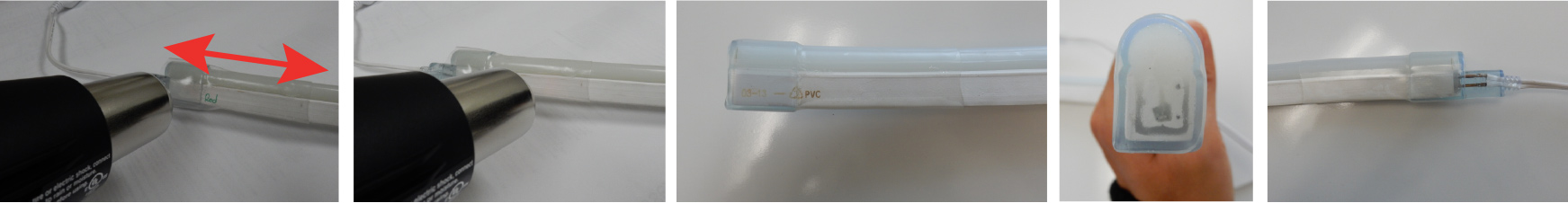
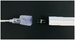
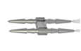
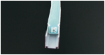
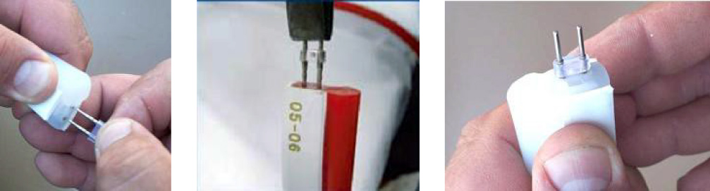
2. Connecting the Power Pin
2. Connecting the Power Pin
Position the LED Flex Neon so that as you look at the cut end the two exposed wires are located on your right hand side. Using flat nosed pliers, position the power pin within the jaws of the pliers with the barbed end of the pin facing
outward.
Position the male power pin so that the ends of the pin line up with the centers of the two exposed wires on the cut face of the LED Flex Neon.
Holding the LED Flex Neon in one hand and the pliers in the other, push the power pin into the exposed wires of the LED Flex Neon with a steady amount of pressure until the clear plastic clip on the power pin seats with the LED Flex Neon.
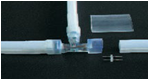
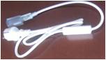
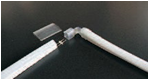
3. Connecting the Power Cord, Connectors and Jumpers
3.Connecting the Power Cord, Connectors and Jumpers
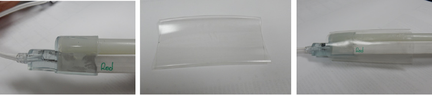
Using your heat gun slightly warm the molded female power feed until slightly malleable. Then position the power cord over the end of the LED Flex Neon and align the smooth ends of the male power pin with the female pin openings in the power cord. Now push the pins into the power cord until a snug/tight fit is attained.
Adding silicon before you connect the cap is recommended for outdoor water roof.
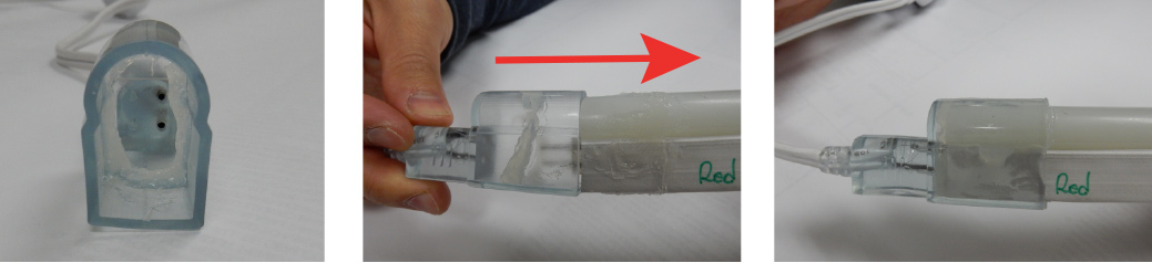
Using the same process described above, place the connector/jumper on the opposite end of the LED Flex Neon using the same installation methods. Once you have completed your run you can terminate the LED Flex Neon using an End- Cap.
Note: Do not energize LED Flex Neon while still warm from heat gun assembly.
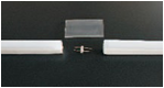
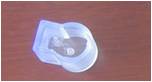
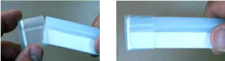
4. Heat Shrink Tubing Placement
4. Heat Shrink Tubing Placement
Place a piece of heat shrink tube over each connection. Place the tube evenly over the join area to be covered on the power cord. On all other connectors (end cap, X, T, L, Inside Corner, Outside Corner etc.) place the shrink tube so that it extends past the end approximately 1/8th of an inch.
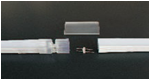
5. Sealing Shrink Tubing
5. Sealing Shrink Tubing
Use a heat gun to shrink the tubing, heating it evenly, until it is snug to the LED Flex Neon and the edges appear to be slightly beading from the glue.
Using even side-to-side motion performs the following: